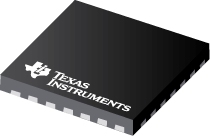
Datasheet Texas Instruments ADS8382IBRHPTG4 — Ficha de datos
| Fabricante | Texas Instruments |
| Serie | ADS8382 |
| Numero de parte | ADS8382IBRHPTG4 |

ADC serie 600KSPS de 18 bits con referencia y pseudo bipolar, entrada totalmente diferencial 28-VQFN -40 a 85
Hojas de datos
ADS8382: 18-Bit 600-kHz Unipolar Differential Input Micropower Sampling ADC datasheet
PDF, 1.7 Mb, Revisión: B, Archivo publicado: nov 3, 2004
Extracto del documento
Precios
Estado
| Estado del ciclo de vida | Activo (Recomendado para nuevos diseños) |
| Disponibilidad de muestra del fabricante | No |
Embalaje
| Pin | 28 | 28 |
| Package Type | RHP | RHP |
| Industry STD Term | VQFN | VQFN |
| JEDEC Code | S-PQFP-N | S-PQFP-N |
| Package QTY | 250 | 250 |
| Carrier | SMALL T&R | SMALL T&R |
| Device Marking | B | ADS8382I |
| Width (mm) | 6 | 6 |
| Length (mm) | 6 | 6 |
| Thickness (mm) | .9 | .9 |
| Pitch (mm) | .65 | .65 |
| Max Height (mm) | 1 | 1 |
| Mechanical Data | Descargar | Descargar |
Paramétricos
| # Input Channels | 1 |
| Analog Voltage AVDD(Max) | 5.25 V |
| Analog Voltage AVDD(Min) | 4.75 V |
| Architecture | SAR |
| Digital Supply(Max) | 5.25 V |
| Digital Supply(Min) | 2.7 V |
| INL(Max) | 3 +/-LSB |
| Input Range(Max) | 4.2 V |
| Input Range(Min) | -4.2 V |
| Input Type | Differential |
| Integrated Features | Oscillator |
| Interface | SPI |
| Multi-Channel Configuration | N/A |
| Operating Temperature Range | -40 to 85 C |
| Package Group | VQFN |
| Package Size: mm2:W x L | 28VQFN: 36 mm2: 6 x 6(VQFN) PKG |
| Power Consumption(Typ) | 115 mW |
| Rating | Catalog |
| Reference Mode | Ext,Int |
| Resolution | 18 Bits |
| SINAD | 96 dB |
| SNR | 96 dB |
| Sample Rate (max) | 600kSPS SPS |
| Sample Rate(Max) | 0.6 MSPS |
| THD(Typ) | -116 dB |
Plan ecológico
| RoHS | Obediente |
Kits de diseño y Módulos de evaluación
- Evaluation Modules & Boards: ADS8382EVM
ADS8382 Evaluation Module
Estado del ciclo de vida: Activo (Recomendado para nuevos diseños)
Notas de aplicación
- Using the ADS8382 With the TMS320C6713 DSPPDF, 193 Kb, Archivo publicado: marzo 24, 2005
This application report presents a solution to interfacing the ADS8382 18-bit, 600-KSPS serial interface converter to the TMS320C6713 DSP. The hardware solution is made up of existing hardware: the ADS8382EVM, 'C6713 DSK, and 5-6K Interface Board. The software demonstrates how to use an EDMA and Timer peripheral to collect data at 598 kHz. Discussed also are some of the key points to remember when - Determining Minimum Acquisition Times for SAR ADCs, part 1 (Rev. A)PDF, 227 Kb, Revisión: A, Archivo publicado: nov 10, 2010
This application report analyzes a simple method for calculating minimum acquisition times for successive-approximation register analog-to-digital converters (SAR ADCs). The input structure of the ADC is examined along with the driving circuit. The voltage on the sampling capacitor is then determined for the case when a step function is applied to the input of the driving circuit. Three different - Determining Minimum Acquisition Times for SAR ADCs, part 2PDF, 215 Kb, Archivo publicado: marzo 17, 2011
The input structure circuit of a successive-approximation register analog-to-digital converter (SAR ADC) incombination with the driving circuit forms a transfer function that can be used to determine minimum acquisition times for different types of applied input signals. This application report, which builds on Determining Minimum Acquisition Times for SAR ADCs When a Step Function is Applied to
Linea modelo
Serie: ADS8382 (3)
- ADS8382IBRHPT ADS8382IBRHPTG4 ADS8382IRHPT
Clasificación del fabricante
- Semiconductors > Data Converters > Analog-to-Digital Converters (ADCs) > Precision ADCs (<=10MSPS)