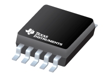
Datasheet Texas Instruments TPS40210DGQG4 — Ficha de datos
| Fabricante | Texas Instruments |
| Serie | TPS40210 |
| Numero de parte | TPS40210DGQG4 |

Amplio rango de entrada Controlador de refuerzo de modo actual 10-MSOP-PowerPAD -40 a 125
Hojas de datos
TPS4021x 4.5-V to 52-V Input Current Mode Boost Controller datasheet
PDF, 1.7 Mb, Revisión: F, Archivo publicado: dic 17, 2014
Extracto del documento
Precios
Estado
| Estado del ciclo de vida | Activo (Recomendado para nuevos diseños) |
| Disponibilidad de muestra del fabricante | Sí |
Embalaje
| Pin | 10 |
| Package Type | DGQ |
| Industry STD Term | HVSSOP |
| JEDEC Code | S-PDSO-G |
| Package QTY | 80 |
| Carrier | TUBE |
| Device Marking | 40210 |
| Width (mm) | 3 |
| Length (mm) | 3 |
| Thickness (mm) | 1.02 |
| Pitch (mm) | .5 |
| Max Height (mm) | 1.1 |
| Mechanical Data | Descargar |
Paramétricos
| Duty Cycle(Max) | 95 % |
| Iout(Max) | 6 A |
| Operating Temperature Range | -40 to 125 C |
| Package Group | MSOP-PowerPAD |
| Rating | Catalog |
| Regulated Outputs | 1 |
| Special Features | Enable,Frequency Synchronization |
| Switch Current Limit(Typ) | 6 A |
| Switching Frequency(Max) | 1000 kHz |
| Switching Frequency(Min) | 35 kHz |
| Type | Controller |
| Vin(Max) | 52 V |
| Vin(Min) | 4.5 V |
| Vout(Max) | 60 V |
| Vout(Min) | 5 V |
Plan ecológico
| RoHS | Obediente |
Kits de diseño y Módulos de evaluación
- Evaluation Modules & Boards: TPS40210EVM
Development Boards/EVMs
Estado del ciclo de vida: Activo (Recomendado para nuevos diseños)
Notas de aplicación
- USB Charger Based on TPS40210 SEPIC ConverterPDF, 389 Kb, Archivo publicado: nov 18, 2008
- Synchronous rectification boosts efficiency by reducing power lossPDF, 145 Kb, Archivo publicado: abr 16, 2013
- New current-mode PWM controllers support boost, flyback, SEPIC and LED-driverPDF, 314 Kb, Archivo publicado: agosto 6, 2008
- Q3 2008 Issue Analog Applications JournalPDF, 1.2 Mb, Archivo publicado: agosto 6, 2008
- Practical Feedback Loop Analysis for Current-Mode Boost ConverterPDF, 557 Kb, Archivo publicado: marzo 7, 2014
- 2Q 2013 Issue Analog Applications JournalPDF, 2.5 Mb, Archivo publicado: abr 16, 2013
- Voltage Fed Full Bridge DC-DC & DC-AC Converter High-Freq Inverter Using C2000 (Rev. B)PDF, 358 Kb, Revisión: B, Archivo publicado: jul 17, 2015
The High-Frequency Inverter is mainly used today in uninterruptible power supply systems, AC motor drives, induction heating and renewable energy source systems. The simplest form of an inverter is the bridge-type, where a power bridge is controlled according to the sinusoidal pulse-width modulation (SPWM) principle and the resulting SPWM wave is filtered to produce the alternating output voltage. - Automated Frequency Response AnalyzerPDF, 939 Kb, Archivo publicado: oct 9, 2013
This application report discusses a new method of doing stability Analysis testing by using basic labequipment, while not requiring any specific instruments. - Basic Calculation of a Boost Converter's Power Stage (Rev. C)PDF, 186 Kb, Revisión: C, Archivo publicado: enero 8, 2014
This application note gives the equations to calculate the power stage of a boost converter built with an IC with integrated switch and operating in continuous conduction mode. It is not intended to give details on the functionality of a boost converter (see Reference 1) or how to compensate a converter. See the references at the end of this document if more detail is needed.
Linea modelo
Serie: TPS40210 (8)
Clasificación del fabricante
- Semiconductors > Power Management > Non-isolated DC/DC Switching Regulator > Step-Up (Boost) > Boost Controller (External Switch)